What is Continuity
Continuity is the process of testing the resistance between two points to determine if they are electrically connected. This testing method ensures the accuracy of connections and detects any unintended connections that may compromise the functionality of the circuit.
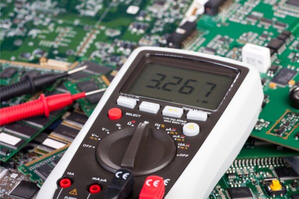
To perform continuity testing, professionals typically use a multimeter set to “continuity” mode, represented by a diode symbol with propagation waves. By touching the probes of the multimeter together, a tone is emitted, indicating a very low resistance (less than a few Ωs) and confirming the electrical connection between the two points.
Continuity testing can be used to verify the conductivity of materials and trace the path of electrical connections. For example, it can determine if two separate ground pins on a breadboard are connected or if there is a proper connection between the VCC pin on a microcontroller and the VCC on a power supply.
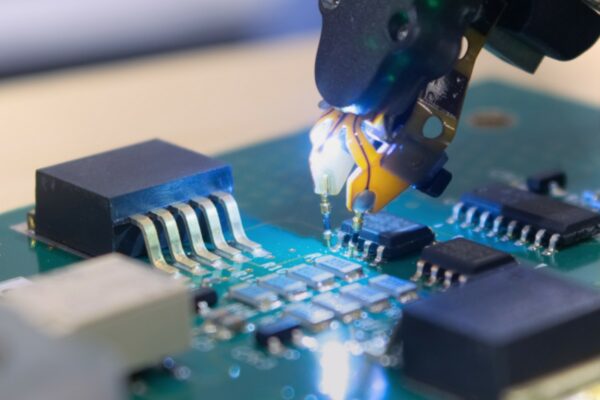
Additionally, continuity testing is valuable for detecting unintended connections, such as when two surface-mount device (SMD) pins are touching. Visual inspection alone may not always identify these connections, making a multimeter a reliable secondary testing resource.
It is also a useful tool for troubleshooting systems. It can help identify issues like shorts between VCC and GND. By powering down the system and checking for continuity between VCC and GND, a beep indicates the presence of a short circuit.
Frequently Asked Questions
Can Ohms Check Continuity
The primary function of an Ohmmeter is to measure the resistance between two points in an electrical circuit. However, it is widely utilized for the purpose of checking continuity as well.
Can I Check Continuity With Voltage
To check for continuity, a multimeter typically applies a small test voltage to the wire and then measures the resulting voltage to determine if there is continuity. However, it’s important to note that if the power is on, the multimeter may not be able to accurately read the test voltage.
