Printed Circuit Board Assemblies (PCBAs) are the heart of modern electronic devices. But how can we be sure that these complex components will function as intended? This is where PCBA test fixtures come into play. This article provides a comprehensive overview of PCBA test fixtures, covering their types, components, operation, design considerations, and advanced technologies. Whether you’re new to the world of electronics manufacturing or a seasoned researcher, this guide will provide you with valuable insights into this critical aspect of quality control.
Understanding PCBA Test Fixtures
Imagine a complex network of roads, intersections, and traffic signals. Before this network can be opened to the public, it needs to be thoroughly tested to ensure smooth and safe traffic flow. Similarly, a PCBA test fixture serves as a custom-designed “checkpoint” for a PCBA, where it’s connected and tested to ensure every component and connection is working correctly.
But what exactly is a PCBA? A PCBA, or Printed Circuit Board Assembly, is a completed electronic assembly that includes a printed circuit board (PCB) with all its components soldered onto it. It’s the foundation upon which our electronic devices are built.
A PCBA test fixture is a specialized device used to test the functionality and performance of these PCBAs. The primary purpose of these fixtures is to ensure that PCBAs meet rigorous quality standards and specifications before they are integrated into final products. They are essential for identifying defects early in the manufacturing process. Catching errors at this stage can significantly reduce costs associated with rework and potential product failures down the line. It’s a proactive approach to quality control that saves time, resources, and reputation.
Types of PCBA Test Fixtures
Just as there are different types of roads designed for various vehicles and traffic conditions, there are different types of PCBA test fixtures tailored to specific testing needs, the complexity of the PCBA, and production volume. Let’s explore some of the most common types:
Manual Test Fixtures
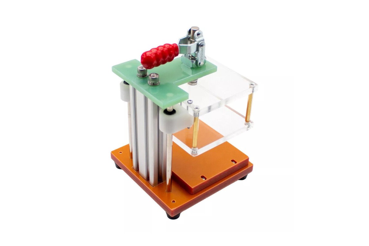
Manual test fixtures are the simplest type, relying on hand operation. In this setup, the PCBA is manually placed and connected for testing. The operator carefully aligns the PCBA with the test probes and applies pressure to establish contact.
While these fixtures boast a low initial cost and are suitable for low-volume production and prototyping, they do have their drawbacks. The testing process is slower compared to automated methods, and there’s a higher risk of operator error. Consequently, they are not ideal for high-volume production environments.
Pneumatic Test Fixtures
Pneumatic test fixtures introduce a degree of automation by using compressed air to apply pressure and create contact between the PCBA and the test probes. The PCBA is placed in the fixture, and pneumatic actuators do the work of pressing the PCBA against the probes.
This method offers a faster testing process and more consistent pressure application than manual fixtures, making them suitable for medium-volume production. However, they come with a higher cost and require an air compressor to operate.
Vacuum Test Fixtures
Vacuum test fixtures take a different approach by using a vacuum to hold the PCBA in place, ensuring excellent contact with the test probes. The PCBA is placed on a bed of nails, and a vacuum is applied, creating a seal that pulls the PCBA down onto the probes.
These fixtures excel in contact reliability and are well-suited for high-volume production. They can even test double-sided PCBs. However, they are more expensive than pneumatic fixtures, require a vacuum pump, and can be complex to design and maintain.
Mechanical Test Fixtures
Mechanical test fixtures employ levers, clamps, or other mechanical mechanisms to apply pressure and make contact. The PCBA is secured in the fixture using these components, which press it against the test probes.
These fixtures are capable of applying high pressure, making them suitable for testing connectors and components that require significant force. However, their design and operation can be complex, and they may not be suitable for all types of PCBAs.
Comparing In-Circuit Testing (ICT) and Functional Testing (FCT) Fixtures
Two primary testing methodologies are often employed: In-Circuit Testing (ICT) and Functional Testing (FCT). Each requires specialized fixtures.
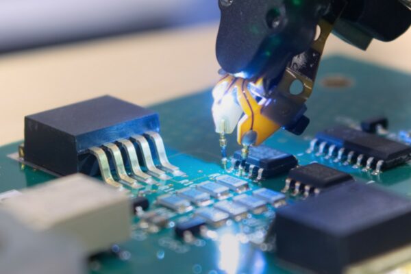
In-Circuit Testing (ICT) focuses on individual components on the PCBA, ensuring they are correctly placed and functioning within specified tolerances. ICT fixtures typically use a “bed of nails” – a set of spring-loaded pins – to contact individual test points on the PCBA. This comprehensive approach can detect a wide range of defects. However, ICT fixtures can be expensive, may require a large number of test probes, and may not detect all functional issues.
Functional Testing (FCT), on the other hand, tests the overall functionality of the PCBA as a complete system. FCT fixtures typically connect to the PCBA’s edge connectors or test points, simulating real-world operating conditions. This method verifies that the PCBA functions as intended and can catch issues that ICT might miss. However, FCT may not detect all component-level defects and can be more complex to design than ICT fixtures.
Key Components of a Test Fixture
Several key components work together to ensure a test fixture functions correctly:
- Test Probes (Pogo Pins): These spring-loaded pins are the critical interface between the test fixture and the PCBA. They come in various tip styles, such as crown, spear, or serrated, each designed for different types of test points. Typically, they are made of beryllium copper or other conductive alloys, often plated with gold for improved conductivity and durability.
- Fixture Base: This is the main structural component, providing support for all other parts. It’s often made of sturdy materials like aluminum, steel, or engineering plastics.
- Top Plate: This component holds the PCBA in place and applies pressure to ensure good contact with the test probes. It’s usually made of materials similar to the fixture base.
- Guide Pins: These ensure proper alignment between the PCBA and the test probes, guaranteeing accurate and repeatable testing.
- Interface Connectors: These connectors link the test fixture to the testing equipment, allowing for the transmission of signals and data.
- Wiring: This connects the test probes to the interface connectors. Proper wire gauge and shielding are crucial considerations to minimize signal interference and ensure accurate test results.
How a PCBA Test Fixture Works
The operation of a PCBA test fixture can be broken down into a series of steps:
- PCBA Placement: The PCBA is carefully placed onto the test fixture, aligning with the guide pins to ensure precise positioning.
- Contact Establishment: The fixture is activated – either manually, pneumatically, or via vacuum – pressing the PCBA against the test probes to establish electrical contact.
- Test Execution: The testing equipment sends signals through the test probes to the PCBA and measures the responses. This is where the actual testing takes place.
- Result Analysis: The testing equipment analyzes the measured responses to determine if the PCBA passes or fails the test, based on predefined criteria.
- PCBA Removal: Once the test is complete, the fixture is deactivated, and the PCBA is removed, ready for the next stage in the manufacturing process.
Advantages and Disadvantages of PCBA Test Fixtures
While PCBA test fixtures offer numerous benefits, they also come with certain drawbacks. Understanding this balance is crucial for making informed decisions about their implementation.
Advantages:
- Improved Product Quality: By ensuring that PCBAs meet quality standards and specifications, test fixtures contribute significantly to the overall quality of the final product.
- Early Defect Detection: Identifying defects early in the manufacturing process minimizes rework and scrap costs, leading to significant savings.
- Increased Throughput: Automated test fixtures can dramatically increase production throughput, enabling faster turnaround times.
- Consistent Test Results: Test fixtures provide consistent and repeatable results, reducing variability and ensuring reliable performance.
- Reduced Labor Costs: Automation reduces the need for manual testing, lowering labor costs and freeing up human resources for other tasks.
Disadvantages:
- High Initial Cost: Test fixtures can be expensive to design and build, especially for complex PCBAs, representing a significant upfront investment.
- Fixture Maintenance: Regular maintenance is required to ensure accuracy and reliability, adding to the ongoing operational costs.
- Limited Flexibility: A dedicated fixture is typically needed for each PCBA design, which can limit flexibility in a dynamic production environment.
- Potential for PCBA Damage: Improperly designed or maintained fixtures can potentially damage PCBAs, leading to costly repairs or replacements.
- Design Complexity: Designing test fixtures for complex PCBAs can be a challenging and time-consuming endeavor, requiring specialized expertise.
Design Considerations for PCBA Test Fixtures
Designing a PCBA test fixture is a complex process that requires careful consideration of various factors. The goal is to create a fixture that is not only effective in testing but also durable, reliable, and cost-effective.
General Considerations
Several general factors influence the design process:
- PCBA Complexity: The number of test points, component density, and the types of signals involved all play a role in determining the complexity of the fixture design.
- Production Volume: High-volume production typically necessitates more robust and automated fixtures to handle the increased throughput.
- Test Requirements: The specific tests to be performed, such as ICT or FCT, dictate the capabilities and features that need to be incorporated into the fixture.
- Accuracy and Repeatability: The fixture must be designed to provide accurate and repeatable test results, ensuring consistent quality control.
- Durability and Longevity: The fixture should be built to withstand repeated use and last for the expected production run, minimizing the need for frequent replacements.
Design for High-Density Interconnect (HDI) PCBs
HDI PCBs present unique challenges due to their smaller features, higher component density, and more complex routing.
To address these challenges, designers may consider:
- Micro-Probes: Using smaller, more precise test probes to access the smaller test points on HDI PCBs.
- High-Precision Alignment: Implementing advanced alignment mechanisms to ensure accurate probe contact with the tiny test points.
- Multi-Stage Fixtures: Employing multiple test stages to access all test points without overcrowding the fixture.
Studies have shown that micro-probes with diameters as small as 75µm can be used to reliably test HDI PCBs, demonstrating the feasibility of testing these advanced designs.
Minimizing Signal Interference and Crosstalk
High-frequency signals and the close proximity of test probes can lead to signal interference and crosstalk, potentially affecting test accuracy.
To mitigate these issues, designers can:
- Use Shielded Probes and Cables: Shielded components help reduce electromagnetic interference (EMI).
- Incorporate Ground Planes: Ground planes in the fixture design provide a low-impedance path for return currents, minimizing interference.
- Design with Controlled Impedance: Controlling impedance helps minimize signal reflections, ensuring signal integrity.
Research indicates that proper grounding and shielding can reduce crosstalk by up to 20dB in high-frequency test fixtures, highlighting the significant impact of these techniques.
Thermal Management in Test Fixtures
High-power components and prolonged testing can generate heat, which can affect test results and even damage the PCBA.
Effective thermal management solutions include:
- Heat Sinks: Using heat sinks to dissipate heat from high-power components.
- Cooling Fans: Incorporating cooling fans to improve airflow and enhance heat dissipation.
- Thermal Sensors: Employing thermal sensors to monitor temperature and trigger cooling mechanisms as needed.
Studies have demonstrated that effective thermal management can maintain PCBA temperature within +/- 5°C during testing, ensuring stable and reliable test conditions.
Material Selection for Optimal Performance
The choice of materials for various fixture components significantly impacts performance.
Probe Materials:
- Beryllium Copper (BeCu): Offers excellent conductivity and spring properties but can be expensive.
- Phosphor Bronze: A more affordable alternative to BeCu, though with slightly lower conductivity.
- Steel: Suitable for high-force applications but has lower conductivity compared to BeCu or phosphor bronze.
Fixture Base and Top Plate Materials:
- Aluminum: Lightweight, offers good thermal conductivity, and is relatively inexpensive.
- Steel: Strong and durable but heavier than aluminum.
- Engineering Plastics (e.g., FR4, G10): Provide good electrical insulation and dimensional stability.
Research suggests that gold-plated BeCu probes offer the best combination of conductivity, durability, and corrosion resistance for most applications, making them a popular choice in the industry.
Choosing the Right PCBA Test Fixture
Selecting the appropriate PCBA test fixture is a critical decision that can impact product quality, production efficiency, and overall costs. Here are some key factors to guide your choice:
Factors to Consider
- PCBA Complexity: Simple PCBAs may only require manual fixtures, while complex designs might necessitate pneumatic or vacuum fixtures.
- Production Volume: High-volume production demands automated fixtures to maximize throughput and efficiency.
- Test Requirements: ICT requires a bed of nails, while FCT may utilize edge connectors or other interfaces, depending on the specific tests.
- Budget: Test fixture costs can vary significantly based on complexity and the level of automation, so budget constraints must be considered.
Decision-Making Process
- Define Test Requirements: Begin by clearly defining the specific tests that need to be performed and the required accuracy for each test.
- Assess PCBA Complexity: Analyze the PCBA’s design, including component density, test point accessibility, and the types of signals involved.
- Estimate Production Volume: Determine the number of PCBAs that need to be tested per day, week, or month to gauge the required throughput.
- Evaluate Fixture Options: Compare different types of fixtures based on their capabilities, cost, and suitability for your specific needs.
- Select the Best Fit: Choose the fixture that best aligns with your test requirements, PCBA complexity, production volume, and budget constraints.
PCBA Test Fixture Maintenance
Regular maintenance is crucial for ensuring the ongoing accuracy, reliability, and longevity of PCBA test fixtures. Neglecting maintenance can lead to inaccurate test results, PCBA damage, and costly downtime.
Importance of Maintenance
Think of a car: regular oil changes, tire rotations, and inspections are essential to keep it running smoothly and prevent major breakdowns. Similarly, test fixtures require routine maintenance to ensure they continue to perform optimally.
Maintenance Tasks
- Probe Cleaning: Test probes should be cleaned regularly to remove debris and oxidation, ensuring good electrical contact.
- Probe Replacement: Worn or damaged probes should be replaced promptly to maintain test accuracy and prevent potential damage to PCBAs.
- Fixture Cleaning: The fixture base, top plate, and other components should be cleaned to prevent contamination that could interfere with testing.
- Alignment Check: Periodically verify the alignment of the PCBA and test probes to ensure proper contact and accurate testing.
- Calibration: Calibrate the test fixture regularly to ensure accurate measurements and reliable test results.
Maintenance Schedule
The frequency of maintenance depends on factors such as production volume, PCBA complexity, and environmental conditions. A high-volume production environment may require more frequent maintenance than a low-volume setting.
Troubleshooting
- Inconsistent Test Results: This may indicate probe contamination, misalignment, or wear.
- PCBA Damage: This could be caused by excessive pressure, misaligned probes, or debris on the fixture.
- Fixture Malfunction: This may be due to mechanical issues, pneumatic or vacuum leaks, or electrical problems.
Advanced PCBA Test Fixture Technologies
The field of PCBA testing is constantly evolving, with new technologies and research pushing the boundaries of what’s possible. This section explores some of the cutting-edge advancements in PCBA test fixture design and operation.
Integration with Boundary Scan and JTAG Testing
Boundary Scan, also known as IEEE 1149.1, is a method for testing interconnections on a PCBA using a serial scan chain. JTAG (Joint Test Action Group) is the common name for this standard.
Integrating boundary scan with test fixtures allows for more comprehensive testing of complex PCBAs, especially those with high-density interconnects. This integration offers several benefits:
- Reduced need for physical test points.
- Improved test coverage for complex circuits.
- Ability to test internal logic and memory devices.
Studies have shown that integrating boundary scan with test fixtures can reduce test time by up to 30% for complex PCBAs, demonstrating the significant efficiency gains possible with this approach.
Wireless and Remote Test Fixture Technologies
Imagine being able to test PCBAs without the need for a tangle of wires. This is the promise of wireless and remote test fixture technologies. These concepts involve using wireless communication to transmit test signals and data between the test fixture and the testing equipment.
The potential benefits are numerous:
- Elimination of physical cables, reducing clutter and improving flexibility.
- Enabling remote testing and monitoring of PCBAs, even in hard-to-reach locations.
- Facilitating testing in harsh or inaccessible environments.
However, challenges remain:
- Ensuring reliable wireless communication in the presence of electromagnetic interference (EMI).
- Maintaining signal integrity over wireless links.
- Powering the wireless components within the test fixture.
Research is ongoing to develop robust and reliable wireless test fixture technologies for various applications, paving the way for more flexible and efficient testing methods.
Test Fixture Design for High-Frequency Applications
Testing high-frequency PCBAs presents unique challenges, requiring specialized test fixtures that can handle high-speed signals without degradation.
Solutions for these challenges include:
- Controlled Impedance Probes and Cables: Using probes and cables with carefully controlled impedance to minimize signal reflections and maintain signal integrity.
- RF Shielding: Implementing RF shielding to prevent interference from external sources, ensuring accurate test results.
- Specialized Probe Materials: Utilizing probe materials with low dielectric loss and high conductivity at high frequencies.
Research has demonstrated that using specialized coaxial probes and RF shielding can enable accurate testing of PCBAs operating at frequencies up to an impressive 40 GHz.
Modeling and Simulation of Test Fixture Performance
What if you could “test drive” a test fixture before it’s even built? This is the power of modeling and simulation. Using computer-aided design (CAD) and simulation software, engineers can model and analyze the performance of a test fixture virtually.
The benefits of this approach are significant:
- Optimize fixture design for improved accuracy and reliability.
- Identify potential design flaws early in the development process, saving time and resources.
- Reduce development time and overall cost.
Various simulation techniques are employed:
- Finite Element Analysis (FEA): Used to model the mechanical behavior of the fixture, ensuring structural integrity.
- Electromagnetic Simulation: Used to analyze signal integrity and EMI, optimizing for accurate testing.
- Thermal Simulation: Used to predict temperature distribution within the fixture, preventing overheating issues.
Studies have shown that using simulation can reduce test fixture development time by up to 50% and improve test accuracy by up to 20%, highlighting the value of this approach.
Test Fixture Data as a Predictive Tool
Here’s an original insight: Test fixture data can be used not only for pass/fail results but also as a powerful predictive tool. By tracking trends in test data – such as slight variations in component values or signal integrity measurements – manufacturers can identify potential problems in the production process before they lead to widespread failures.
This predictive approach allows for proactive adjustments to the manufacturing process, optimizing production, improving yields, and ultimately reducing costs. It’s a shift from reactive to proactive quality control, leveraging data to drive continuous improvement.
