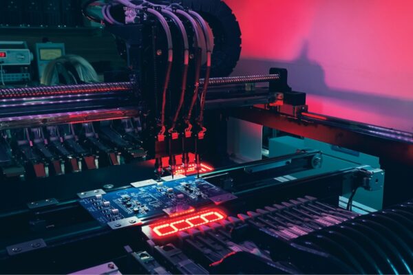
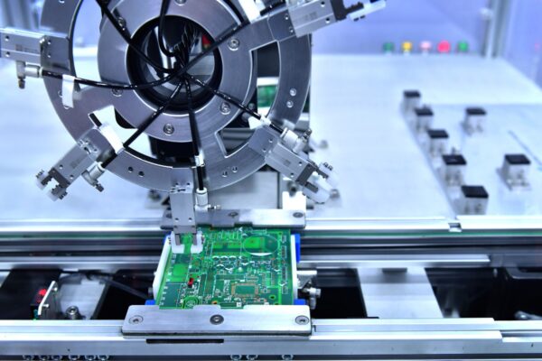
In the intricate world of electronics manufacturing, ensuring the quality and reliability of every component is paramount. One crucial aspect of this quality control process is the functional testing of Printed Circuit Board Assemblies (PCBAs). But what exactly is a PCBA functional tester, and why is it so important? This article delves into the world of PCBA functional testers, exploring their purpose, types, components, operation, benefits, and limitations. Whether you’re new to the field or a seasoned researcher, this guide offers a comprehensive overview of this essential technology.
What is a PCBA Functional Tester
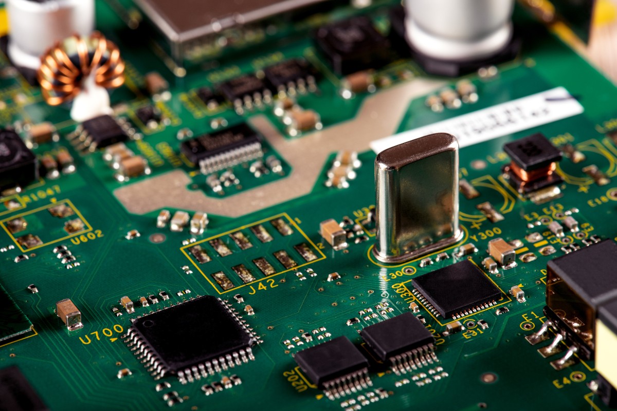
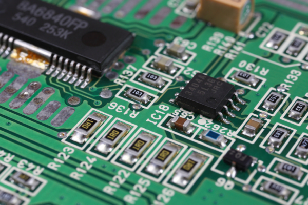
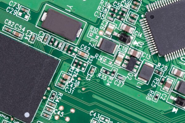
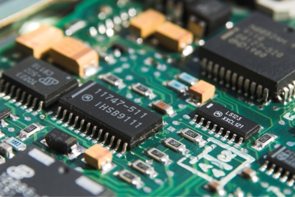
Let’s start with the basics. PCBA stands for Printed Circuit Board Assembly. It refers to a circuit board that has all its electronic components, such as resistors, capacitors, and integrated circuits, soldered onto it. It’s the heart of most electronic devices, from smartphones to industrial control systems.
A PCBA functional tester is a sophisticated system used to verify that a PCBA operates correctly according to its specifications. It’s like a final exam for the assembled board. The tester applies power and signals to the PCBA and measures its responses to ensure that it functions as intended. Think of it as a doctor checking a patient’s vital signs. Just as a doctor uses various instruments to assess a patient’s health, a functional tester uses a variety of tools to evaluate the “health” of a PCBA. These testers are essential in electronics manufacturing to detect defects that may have occurred during the assembly process, such as incorrect component placement, faulty soldering, or internal shorts.
The primary goal? To catch faulty PCBAs before they are shipped to customers, ensuring product quality and reliability. This is not just about avoiding minor glitches; it’s about ensuring that the devices we rely on every day function flawlessly.
Why is Testing PCBAs Important?
Testing PCBAs is not just a formality; it’s a critical step in the manufacturing process that has far-reaching implications. Let’s explore why:
Ensuring Product Quality: This is the most obvious reason. Testing helps identify manufacturing defects, preventing faulty products from reaching customers. Imagine buying a new phone only to find that the camera doesn’t work. Rigorous testing aims to eliminate such issues.
Reducing Field Failures: Catching defects early reduces the likelihood of products failing in the field. Field failures can be incredibly costly for companies, not just in terms of repairs but also in terms of damage to their reputation. A product that fails prematurely can erode customer trust and lead to negative reviews.
Improving Reliability: Thorough testing leads to more reliable products. Reliability is a key factor in customer satisfaction and brand loyalty. Customers are more likely to stick with a brand that consistently delivers reliable products.
Cost Savings: Identifying and fixing defects during manufacturing is significantly cheaper than dealing with returns, repairs, and warranty claims. The cost of a product recall, for example, can be astronomical.
Maintaining Brand Reputation: Delivering high-quality, reliable products helps maintain a positive brand image. In today’s competitive market, a company’s reputation is one of its most valuable assets.
Types of PCBA Functional Testers
Several types of PCBA functional testers are available, each with its own strengths and weaknesses. Here’s a brief overview:
In-Circuit Testers (ICT): These testers check individual components on a PCBA while they are in-circuit (soldered onto the board). They use a “bed of nails” fixture to make contact with test points on the board. ICTs are great at finding manufacturing defects like incorrect component placement or solder joint problems.
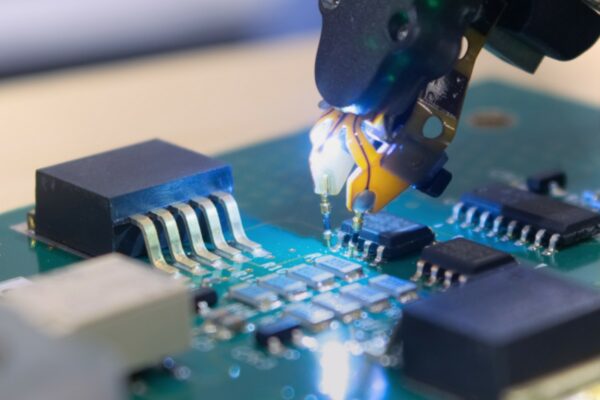
Flying Probe Testers: These testers use a small number of probes that move around the board to make contact with test points. They don’t require a dedicated fixture, making them more flexible than ICTs. They are suitable for low-volume production and prototype testing.
Automated Optical Inspection (AOI): AOI systems use cameras to capture images of the PCBA and analyze them for defects. They can detect problems such as missing components or incorrect component orientation. AOI is often used as a first-pass inspection to quickly identify obvious visual defects.
X-ray Inspection: X-ray inspection systems use X-rays to create images of the internal structure of the PCBA. They can detect hidden defects such as voids in solder joints or problems with ball grid array (BGA) packages. This type of inspection is crucial for high-reliability applications.
Functional Circuit Testers: These testers verify the overall functionality of the PCBA by applying power and signals and measuring its responses. They simulate the actual operating environment of the PCBA, ensuring it meets its performance specifications.
In-depth Analysis of Each Type
Let’s take a closer look at each type of tester:
In-Circuit Testers (ICT)
- Strengths: ICTs offer high fault coverage, especially for analog components. They are fast and well-suited for high-volume production environments.
- Weaknesses: Developing fixtures for ICTs can be expensive. They also have limited functional testing capabilities and may face challenges with high-density boards.
- Best Use Cases: ICTs are ideal for high-volume production of boards with a significant number of analog components.
Flying Probe Testers
- Strengths: Flying probe testers eliminate the need for expensive fixtures. They offer flexibility for different board designs and are well-suited for prototypes and low-volume production.
- Weaknesses: They have slower test times compared to ICTs and may offer limited fault coverage. They can also face challenges with very high-speed signals.
- Best Use Cases: Flying probe testers are best for prototype testing, low-volume production, and boards with limited test access.
Automated Optical Inspection (AOI)
- Strengths: AOI systems are fast, non-contact, and effective for detecting visual defects. They are also relatively low-cost.
- Weaknesses: They are limited to visible defects and can be sensitive to lighting and board color variations.
- Best Use Cases: AOI is ideal for first-pass inspection, process monitoring, and detecting gross assembly errors.
X-ray Inspection
- Strengths: X-ray inspection can detect hidden defects, making it essential for BGA and other complex packages. It offers high reliability in inspection results.
- Weaknesses: X-ray equipment is expensive and requires specialized training to operate. It is also slower than AOI.
- Best Use Cases: X-ray inspection is crucial for high-reliability applications, inspection of complex packages, and failure analysis.
Functional Circuit Testers
- Strengths: Functional testers verify the overall functionality of the PCBA, simulating real-world operation. They can be customized for specific applications.
- Weaknesses: They can be complex to program and may not pinpoint the exact location of a defect. Test times can vary depending on the complexity of the PCBA.
- Best Use Cases: Functional testers are ideal for end-of-line testing, ensuring that the product meets performance specifications, and testing complex digital circuits.
Test Fixture
The test fixture is a critical component of a PCBA functional tester. It’s a mechanical device that holds the PCBA in place and provides electrical connections to the tester. Imagine it as a custom-made docking station for the PCBA. A typical fixture consists of a base plate, a top plate, and a set of spring-loaded test probes, often called pogo pins. The fixture is meticulously designed to align the PCBA precisely with the probes, ensuring reliable contact.
Test Fixture Design Considerations
Designing a test fixture is a complex process that requires careful consideration of several factors:
Board Layout: The fixture must be designed to accommodate the specific layout of the PCBA, including the location of test points and components. Each PCBA design is unique, requiring a custom fixture.
Probe Placement: Probes must be placed strategically to access all necessary test points without interfering with components. This requires careful planning and precision.
Signal Integrity: For high-speed circuits, the fixture must be designed to minimize signal reflections and crosstalk. This may involve using impedance-controlled probes and careful routing of traces within the fixture. This is a more complex consideration often overlooked, but it is critical in modern high-speed electronics.
Durability: The fixture must be able to withstand repeated use without degrading performance. Test fixtures are often used thousands of times, so they need to be built to last.
Ease of Use: The fixture should be easy to load and unload the PCBA, minimizing operator fatigue and potential damage to the board. A well-designed fixture can significantly improve the efficiency of the testing process.
Test Probes
Test probes, also known as pogo pins, are the unsung heroes of the functional testing process. They are spring-loaded contacts that make electrical connections between the tester and the PCBA. These tiny probes are designed to compress when the PCBA is pressed against them, ensuring good contact even if the board is slightly warped.
Different types of probes are available for different applications. For example, high-current probes are used for power circuits, while high-frequency probes are used for high-speed signals. There are also probes designed specifically for accessing small test points. Probe tips can be made from various materials, such as beryllium copper or gold, depending on the application requirements. The choice of probe material can affect the longevity and reliability of the connection.
Measurement Instruments
Functional testers rely on a variety of measurement instruments to apply signals and measure the responses of the PCBA. These instruments are the workhorses of the testing process, providing the data needed to determine if the PCBA is functioning correctly. Here are some commonly used instruments:
Digital Multimeters (DMMs): These versatile instruments measure voltage, current, and resistance. They are essential for basic electrical measurements.
Oscilloscopes: Oscilloscopes display waveforms of electrical signals, allowing engineers to visualize the behavior of the circuit over time. They are crucial for analyzing signal integrity and detecting timing issues.
Power Supplies: Power supplies provide the necessary power to the PCBA during testing. They can be programmed to deliver specific voltages and currents.
Signal Generators: Signal generators create various types of electrical signals, such as sine waves, square waves, and pulses. These signals are used to stimulate the PCBA and test its response to different inputs.
Logic Analyzers: Logic analyzers capture and analyze digital signals. They are particularly useful for debugging complex digital circuits.
Specialized Instruments: Depending on the application, functional testers may also include specialized instruments such as RF signal generators, spectrum analyzers, and network analyzers. These instruments are used for testing specific types of circuits, such as radio frequency (RF) or communication circuits.
Software and Control System
The software and control system is the brain of the functional tester. It orchestrates the entire testing process, controlling the operation of the tester, executing the test program, acquiring data from the measurement instruments, and analyzing the results. It’s like the conductor of an orchestra, ensuring that all the instruments play in harmony.
The software typically includes a graphical user interface (GUI) that allows the operator to interact with the tester. This GUI provides a user-friendly way to control the tester, monitor the testing process, and view the results. Test programs are written in a specialized programming language or using a graphical programming environment. These programs define the sequence of tests to be performed, the signals to be applied, and the measurements to be taken.
The software may also include features for data logging, report generation, and statistical process control. Data logging allows engineers to track the performance of PCBAs over time, while report generation provides a detailed summary of the test results. Statistical process control (SPC) uses statistical methods to monitor and control the manufacturing process, helping to identify trends and prevent defects.
How Does a PCBA Functional Tester Work?
Have you ever wondered what happens behind the scenes during a PCBA functional test? Let’s break down the process step-by-step:
Functional Testing Process
- Loading: The PCBA is carefully loaded into the test fixture.
- Connection: The test probes make contact with the test points on the PCBA, establishing electrical connections.
- Power Up: The tester applies power to the PCBA, bringing it to life.
- Test Execution: The tester executes the test program, which applies a sequence of signals to the PCBA and measures its responses. This is where the real testing begins.
- Data Acquisition: The measurement instruments capture the signals from the PCBA, collecting the raw data.
- Data Analysis: The software analyzes the data, comparing it to the expected values to determine if the PCBA is functioning correctly.
- Pass/Fail Determination: Based on the analysis, the software determines whether the PCBA passes or fails the test. This is the moment of truth.
- Reporting: The tester generates a report that indicates the test results, including any failures that were detected. This report provides valuable information for debugging and process improvement.
- Unloading: The PCBA is unloaded from the fixture, ready for the next stage in the manufacturing process.
Advanced Functional Testing Techniques
Beyond the basic process, there are several advanced techniques used in functional testing:
Boundary Scan (JTAG): This is a technique for testing interconnections between integrated circuits on a PCBA. It uses a dedicated test bus to shift data into and out of the ICs, allowing the tester to verify the connections between them.
In-System Programming (ISP): This is a method for programming or configuring devices on a PCBA while they are in-circuit. Functional testers can be used to perform ISP, allowing them to update firmware or configure programmable logic devices.
Protocol-Aware Testing: This is a technique for testing communication interfaces on a PCBA, such as USB, Ethernet, or CAN bus. The tester emulates the communication protocol and verifies that the PCBA can communicate correctly with other devices.
Benefits of Using PCBA Functional Testers
The advantages of using PCBA functional testers are numerous and contribute significantly to the overall quality and efficiency of electronics manufacturing:
Improved Product Quality: Functional testing helps ensure that PCBAs meet their performance specifications. This rigorous testing leads to higher quality products that are less likely to have defects or malfunctions.
Reduced Testing Time: Automated functional testers can test PCBAs much faster than manual testing methods. This speed significantly reduces production time and allows for faster time-to-market.
Cost Savings: Early detection of defects reduces rework, scrap, and warranty costs. By catching problems early, manufacturers can save significant amounts of money in the long run.
Enhanced Reliability: Thorough testing leads to more reliable products that are less likely to fail in the field. This improved reliability enhances customer satisfaction and reduces the likelihood of costly product recalls.
Data-Driven Insights: Functional testers can collect data that can be used to improve the manufacturing process and product design. This data can be analyzed to identify trends, optimize processes, and prevent future defects. This is a less obvious but increasingly important benefit, especially with the rise of data analytics in manufacturing.
Scalability: Functional testing can be scaled to meet the needs of different production volumes. Whether you’re producing a small batch of prototypes or a large volume of consumer electronics, functional testing can be adapted to your needs.
Limitations of PCBA Functional Testers
While PCBA functional testers offer many benefits, they also have some limitations:
Fixture Costs: Developing custom test fixtures can be expensive, especially for complex boards. This cost can be a barrier to entry for smaller manufacturers or for those producing a wide variety of boards.
Programming Complexity: Writing test programs can be time-consuming and require specialized skills. This complexity can add to the overall development time and cost.
Test Coverage Limitations: Functional testers may not be able to test every aspect of a PCBA, especially for very complex designs. There may be certain functions or components that are difficult or impossible to test using a functional tester.
Debugging Challenges: When a PCBA fails a functional test, it can be difficult to pinpoint the exact cause of the failure. This can lead to time-consuming debugging efforts.
Maintenance Requirements: Functional testers require regular calibration and maintenance to ensure accuracy. This ongoing maintenance can add to the overall cost of ownership.
Choosing the Right PCBA Functional Tester
Selecting the right PCBA functional tester is a crucial decision that can significantly impact the efficiency and effectiveness of your testing process. Here are some key factors to consider:
Board Complexity: Consider the complexity of the PCBAs that need to be tested. This includes the number of components, the types of components (analog, digital, mixed-signal), and the density of the board. More complex boards may require more sophisticated testers.
Production Volume: Choose a tester that is appropriate for your production volume. Flying probe testers are suitable for low-volume production or prototyping, while ICTs are better for high-volume production.
Budget Constraints: Functional testers can range in price from a few thousand dollars to hundreds of thousands of dollars. Determine your budget and choose a tester that fits within that budget.
Test Requirements: Consider the specific test requirements, such as the types of tests that need to be performed (e.g., voltage measurements, frequency measurements, digital signal analysis), the accuracy requirements, and the speed requirements.
Technical Support: Choose a vendor that offers good technical support and training. This is crucial for ensuring that you can effectively use and maintain the tester.
Future Needs: Consider the potential for future growth and choose a tester that can be expanded or upgraded to meet future needs. This is especially important if you anticipate changes in your product designs or production volume. Choosing a scalable solution can save you from having to replace your tester prematurely.
PCBA Functional Tester Setup Process
Setting up a PCBA functional tester involves several key steps:
Fixture Design and Fabrication:
- Analyze the PCBA design and identify test points.
- Design the test fixture using CAD software.
- Fabricate the fixture using materials such as FR-4, aluminum, or acrylic.
- Install the test probes in the fixture.
Test Program Development:
- Define the test requirements and specifications.
- Write the test program using a specialized programming language or a graphical programming environment.
- Debug the test program using a simulator or a prototype PCBA.
System Integration and Calibration:
- Install the software on the tester’s computer.
- Connect the measurement instruments to the tester.
- Load the test fixture onto the tester.
- Calibrate the tester using a known-good PCBA or a calibration artifact.
PCBA Functional Tester Maintenance
Proper maintenance is essential for ensuring the accuracy and longevity of a PCBA functional tester:
Regular Calibration: Functional testers should be calibrated regularly to ensure accuracy. The calibration interval depends on the specific tester and the application requirements.
Probe Cleaning and Replacement: Test probes should be cleaned regularly to remove debris and ensure good contact. Probes should be replaced when they become worn or damaged.
Software Updates: Keep the tester’s software up to date to ensure compatibility with the latest operating systems and to take advantage of new features and bug fixes.
Preventive Maintenance: Perform regular preventive maintenance on the tester, such as checking cables, connectors, and power supplies.
Comparing Functional Testing with Other Methods
Functional testing is just one of several methods used to test PCBAs. Here’s how it compares to other common methods:
Manual Testing:
- Advantages: Low initial cost, flexible, can be used for any type of PCBA.
- Disadvantages: Slow, labor-intensive, prone to human error, not suitable for high-volume production.
In-Circuit Testing (ICT):
- Advantages: High fault coverage for analog components, fast test times, good for high-volume production.
- Disadvantages: High fixture costs, limited functional testing capabilities, challenges with high-density boards.
Burn-In Testing:
- Advantages: Can detect early-life failures, improves product reliability.
- Disadvantages: Time-consuming, can stress components, may not be suitable for all applications.
Functional Testing:
- Advantages: Verifies overall functionality, simulates real-world operation, can be customized for specific applications.
- Disadvantages: Can be complex to program, may not pinpoint exact defect location, test times can vary depending on complexity.
Industry Standards for Functional Testing
Several industry standards provide guidelines and requirements for functional testing:
- IPC-9252: Guidelines for Electrical Testing of Unpopulated Printed Boards
- IPC-7351: Generic Requirements for Surface Mount Design and Land Pattern Standard
- JEDEC Standards: Various standards related to semiconductor testing
- MIL-STD-883: Test Method Standard for Microcircuits
- MIL-PRF-38534: Performance Specification for Hybrid Microcircuits
- MIL-PRF-38535: Performance Specification for Integrated Circuits (Microcircuits) Manufacturing
These standards help ensure consistency and reliability in functional testing across the industry.
