Circuit card assembly (CCA) is a fundamental technology in modern electronics, serving as the foundation for countless devices we use daily. This guide explores the components, manufacturing processes, applications, and challenges of CCAs, providing insights for electronics enthusiasts, engineers, and anyone curious about the inner workings of electronic devices.
What is a Circuit Card Assembly
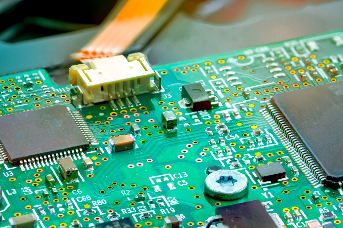
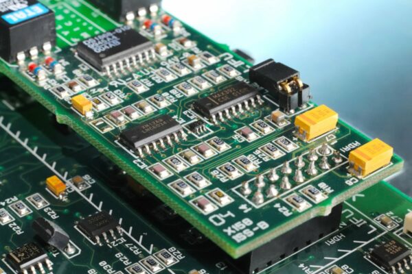
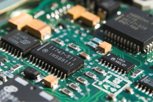
A CCA is a fully assembled printed circuit board (PCB) with all its components soldered in place. It represents the final, functional form of an electronic circuit, ready for system integration. CCAs are often referred to as PCBAs (Printed Circuit Board Assemblies), though both terms describe the same concept.
Basic Structure of a CCA
A CCA’s structure is deceptively simple, yet supports complex electronic systems through its layered construction and intricate design. The primary elements of a typical CCA include:
- Substrate: The foundation of the CCA, typically made of fiberglass-reinforced epoxy laminate material, providing mechanical support and electrical insulation.
- Copper Traces: Thin layers of copper etched onto the substrate, forming conductive pathways that connect different components.
- Solder Mask: A thin, protective layer covering the copper traces, preventing oxidation and reducing short circuit risks.
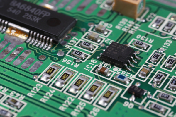
- Silkscreen: The topmost layer featuring symbols, text, and component designators that aid in assembly and troubleshooting.
Important Components of a CCA
The core functionality of a CCA resides in its components, which bring the circuit to life when properly arranged and connected. Active components, such as integrated circuits (ICs), transistors, and diodes, form the core of the CCA’s functionality. ICs, ranging from simple logic gates to powerful microprocessors, are the operational brains. Transistors act as switches or amplifiers, controlling current flow, while diodes allow one-directional current flow, essential for signal rectification and protection.
Passive components, including resistors, capacitors, and inductors, play crucial supporting roles. Resistors limit current flow, controlling voltage levels and current distribution. Capacitors store and release electrical energy, vital for filtering, smoothing, and timing applications. Inductors store energy in magnetic fields, useful for filtering and energy storage in power supplies.
Onboard Connectors
Connectors are essential in CCAs, enabling communication between the board and external components or other circuit boards. Board-to-board connectors allow multiple CCAs to be interconnected, essential for modular designs and complex systems. I/O connectors facilitate communication between the CCA and external devices or user interfaces. Wire-to-board connectors connect external wiring to the CCA, often used for power supply or signal transmission from sensors or actuators. High-frequency connectors are specialized for maintaining signal integrity in high-frequency applications, such as RF and microwave circuits.
Types of Circuit Card Assemblies and PCBs
Types of Circuit Card Assemblies
Box Build Assembly
Box build assembly goes beyond the basic PCBA, incorporating the circuit board into a complete enclosure. It typically includes the fully assembled PCB, electronic and electromechanical components, custom cable assemblies, power sources, and thermal management solutions like heatsinks. Often called “systems integration,” box build assemblies represent complete, self-contained electronic systems ready for deployment.
Surface Mount Technology (SMT) Assembly
SMT has revolutionized CCA manufacturing by placing components directly onto the PCB surface. This method offers several advantages, including more compact designs, higher component density, easier automation, and support for smaller components, leading to device miniaturization.
Through-Hole Assembly
Although SMT has become dominant, through-hole assembly remains crucial in certain areas. This method involves inserting component leads through holes in the PCB and soldering them on the opposite side. It offers greater mechanical strength, ideal for components under mechanical stress, better heat dissipation for high-power components, and easier manual rework and repair.
PCB Types
Single-sided PCBs
Single-sided PCBs are the simplest form, with components and copper traces on only one side. They are cost-effective and suitable for simple, low-density circuits.
Double-sided PCBs
Double-sided PCBs feature copper layers on both sides of the substrate, offering increased circuit density and routing flexibility. They often use plated through-holes to connect the two sides.
Multi-layer PCBs
Multi-layer PCBs consist of multiple copper layers separated by insulation. They can have anywhere from 4 to 12 or more layers, allowing for extremely high component density and complex routing schemes. This design accommodates complex circuitry in compact spaces.
Rigid PCBs
Rigid PCBs are the standard inflexible boards used in most electronic devices, providing a stable platform for components and suitable for a wide range of applications.
Flexible PCBs
Flexible PCBs are made with a flexible substrate, allowing them to bend or flex. They are ideal for applications with space constraints, devices requiring movement or folding, and reducing device weight.
Rigid-Flex PCBs
Rigid-Flex PCBs combine rigid and flexible sections, often used in applications requiring a compact form factor with some flexibility, such as smartphones or wearables.
Specialized PCB Types
High-Density Interconnect (HDI) PCBs push miniaturization boundaries with finer lines and spaces, smaller vias and capture pads, and higher connection pad density. These characteristics make HDI PCBs ideal for compact, high-performance devices like smartphones and tablets. Metal Core PCBs incorporate a metal (usually aluminum) base that conducts heat away from components, making them suitable for high-power LED lighting and automotive applications.
Mixed Technology Assemblies
Many modern electronic devices use a combination of assembly technologies to optimize performance, cost, and manufacturability. Mixed technology assemblies typically combine SMT for most components with through-hole technology for connectors, high-power components, or parts requiring additional mechanical strength. This approach leverages the advantages of both technologies, creating CCAs that are both compact and robust.
Circuit Card Assembly Manufacturing Process
Design Phase
- Schematic Design: The first step in creating a CCA is developing a schematic design, a detailed diagram that guides the entire circuitry. It includes all electronic components, their connections, and specifications.
- Board Design Layout: Once the schematic is complete, specialized PCB design software translates the schematic into a physical layout. This involves placing components, routing traces, and ensuring proper clearances and adherence to design rules.
- Design for Manufacturing (DFM) Check: Before production, a DFM check is crucial to ensure efficient and reliable manufacturing. This involves analyzing the design for potential manufacturing issues, ensuring compliance with manufacturing capabilities, and identifying and correcting possible design errors.
PCB Fabrication
- Material Selection: Substrate material choice is critical and depends on the application. Common materials include FR-4 for standard applications, high-frequency materials for RF applications, and polyimide for flexible PCBs.
- Layer Stacking: For multi-layer PCBs, the individual layers are stacked and bonded together under heat and pressure.
- Drilling: Holes are drilled for vias and through-hole components using high-speed drill bits or lasers for smaller holes.
- Copper Plating: The board is plated with copper to create conductive paths between layers.
- Etching: Excess copper is removed, leaving the desired circuit pattern.
- Solder Mask and Silkscreen Application: The solder mask and silkscreen layers are applied to protect the copper and provide component identification.
Component Preparation
- Component Sourcing: All necessary components are sourced according to the bill of materials (BOM).
- Component Verification: Each component is verified for correctness and quality.
- Solder Paste Application: For surface-mount components, solder paste is applied to the board using a stencil. This process requires precision, as the amount and placement of solder paste affects the final assembly quality.
Soldering Processes
Reflow Soldering
Used primarily for surface-mount components, reflow soldering involves placing components on the board with solder paste, then passing the board through a reflow oven. The process includes carefully controlled heating stages to melt and cool the solder, forming reliable connections.
Wave Soldering
Primarily used for through-hole components, wave soldering involves inserting components into the board and passing it over a wave of molten solder. The solder adheres to exposed metal surfaces, creating connections.
Selective Soldering
For boards with a mix of SMT and through-hole components, selective soldering allows precise solder application to specific areas.
Inspection and Testing
Automated Optical Inspection (AOI)
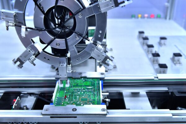
AOI systems use high-speed cameras and image processing software to detect visible defects such as missing components, incorrect placements, or solder joint issues.
X-Ray Inspection
X-ray inspection is particularly useful for inspecting hidden solder joints, such as those under BGAs.
In-Circuit Testing (ICT)
Electrical tests are performed to check for shorts, opens, and component values.
Functional Testing
The CCA is tested to ensure it performs its intended functions correctly.
Post-Assembly Processes
- Conformal Coating: A protective coating may be applied to protect the CCA from environmental factors such as moisture, dust, or chemicals.
- Final Inspection: A thorough visual and functional inspection is performed to ensure the CCA meets quality standards.
- Packaging: The completed CCAs are carefully packaged for protection during shipping and storage.
Advanced Manufacturing Techniques
With technological advancements, new manufacturing techniques are emerging to improve efficiency, quality, and capabilities in CCA production. 3D printing is being explored for creating custom enclosures or even certain PCB structures. AI algorithms are being employed to enhance defect detection and predict potential manufacturing issues. The integration of Industry 4.0 principles, including real-time data analysis and automated decision-making, is improving overall production efficiency and quality.
Quality Control and Testing in Circuit Card Assembly
Visual Inspection
Visual inspection is often the first line of defense against defects. Manual inspection involves trained technicians visually examining CCAs for obvious defects such as missing or misaligned components, solder bridges, and visible damage. While effective, manual inspection is limited by human factors. To overcome these limitations, manufacturers employ AOI systems. These machines use high-resolution cameras and advanced image processing algorithms to detect defects that might be missed by the human eye, such as component presence and correct orientation, solder joint quality, and correct component values.
X-Ray Inspection
X-ray inspection is valuable for inspecting hidden solder joints, especially in BGAs and other leadless packages. It can detect voids in solder joints and identify internal defects in multi-layer PCBs. Advanced X-ray systems can even create 3D images of solder joints, allowing for detailed analysis of joint quality.
Electrical Testing
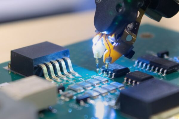
Electrical testing verifies CCA functionality beyond what visual and X-ray inspections can reveal. ICT uses a bed-of-nails fixture to contact test points on the CCA, testing individual components for presence, correct values, and basic functionality. Flying Probe Testing offers a flexible alternative for lower volume production or prototypes, using moving probes to contact test points. Functional testing checks the overall performance of the CCA by powering up the board, simulating real-world inputs, and verifying that all outputs and functions meet specifications.
Environmental Stress Screening
Environmental Stress Screening (ESS) subjects CCAs to controlled stress conditions to identify potential weaknesses. Thermal cycling rapidly changes temperatures to reveal issues with solder joints, component attachments, and board materials. Vibration testing simulates mechanical stresses a CCA might experience during transportation or in its final application. Humidity testing exposes the CCA to high humidity to check for potential corrosion or short circuit issues.
Quality Standards and Certifications
To ensure consistent quality, several standards and certifications have been developed. The IPC provides widely recognized standards such as IPC-A-610 for acceptability of electronic assemblies and IPC-J-STD-001 for requirements for soldered electrical and electronic assemblies. ISO 9001:2015 is an international standard for quality management systems that helps organizations demonstrate their ability to consistently provide products that meet customer and regulatory requirements.
Advanced Quality Control Techniques
As technology advances, new quality control techniques are being developed to further improve CCA reliability and performance. 3D AOI systems provide more comprehensive inspection capabilities, including measurement of component height and coplanarity, detection of lifted leads or components, and improved solder joint inspection. Statistical Process Control (SPC) helps identify trends and potential issues before they result in defects by collecting and analyzing data from various manufacturing stages. Machine learning algorithms are being employed to improve defect detection accuracy and speed, learning from historical data to identify even subtle anomalies.
Cleanliness Testing
In many high-reliability applications, CCA cleanliness is crucial. Ion contamination testing measures CCA cleanliness by washing the board with a solvent and measuring the ionic content of the resulting solution. The results indicate the level of potentially harmful residues, allowing manufacturers to verify cleaning process effectiveness.
Design for Testing (DFT)
Quality control begins at the design stage with DFT principles. These include incorporating strategically placed test points for easier access during testing, implementing boundary scan (JTAG) capabilities in ICs for improved testability of complex digital circuits, and designing CCAs with modular, easily testable subsections to simplify troubleshooting and repair.
Applications and Advantages of Circuit Card Assemblies
Consumer Electronics Applications
What powers the vast array of consumer electronic devices we use every day? Circuit card assemblies. In smartphones and tablets, CCAs are marvels of miniaturization, packing powerful processors, memory, and various sensors into incredibly compact spaces. Laptops and PCs rely on CCAs for their motherboards, graphics cards, and various peripheral components. The IoT revolution has been made possible by small, efficient CCAs integrated into smart home devices, from thermostats to voice-controlled assistants. Modern televisions incorporate sophisticated CCAs that handle not just display driving, but also smart features, audio processing, and connectivity. Wearable technology, such as smartwatches and fitness trackers, represents some of the most challenging applications for CCAs, requiring extreme miniaturization and power efficiency.
Industrial and Commercial Applications
Medical Equipment
In the medical field, CCAs play a critical role in various devices, meeting stringent regulatory requirements. Applications include imaging systems like MRI and CT scanners, patient monitors, diagnostic equipment, and implantable medical devices. The reliability and precision of CCAs are paramount in these life-critical applications.
Automotive Electronics
Modern vehicles are essentially computers on wheels, with CCAs controlling everything from engine management to infotainment systems. Applications include Engine Control Units (ECUs), Advanced Driver Assistance Systems (ADAS), in-car entertainment and navigation systems, and electric vehicle battery management systems. CCAs in automotive applications must withstand harsh environmental conditions and meet strict reliability standards.
Aerospace and Defense
The aerospace and defense sector demands CCAs that can perform reliably under extreme conditions. Applications include avionics systems, satellite communications, radar and sonar systems, and guidance systems for missiles and drones. CCAs in this sector often need to meet military specifications for durability and performance.
Telecommunications
The backbone of our connected world relies heavily on CCAs. Applications include network routers and switches, base stations for cellular networks, fiber optic communication equipment, and satellite communication ground stations. CCAs in telecommunications equipment must handle high data rates and maintain signal integrity over long distances.
Specialized Applications
High-Frequency RF Circuits
Used in wireless communications, these CCAs require careful design to maintain signal integrity at high frequencies. Applications include 5G network equipment, radar systems, and satellite communications. The design of these CCAs often involves specialized materials and layout techniques to minimize signal loss and interference.
Power Electronics
CCAs designed for power applications must handle high currents and voltages efficiently. Areas include inverters for solar power systems, motor controllers for industrial equipment, and power supplies for data centers. These CCAs often incorporate specialized cooling solutions and robust components to handle the high power levels.
Flexible Electronics
This emerging field uses flexible CCAs to create bendable or stretchable electronic devices. Applications include wearable medical sensors, flexible displays, and smart textiles. Flexible CCAs open up new possibilities for integrating electronics into unconventional form factors and materials.
Advantages of Using CCAs
CCAs offer several advantages that make them indispensable in modern electronic design. They reduce the overall size and weight of electronic devices by integrating multiple components onto a single board, which is particularly crucial in applications like aerospace and mobile devices. The use of automated assembly processes and standardized design practices leads to more consistent and reliable products, especially important in critical applications like medical devices and automotive systems. Once the initial design and setup costs are covered, CCAs can be produced in large quantities very efficiently, reducing per-unit costs. The short, optimized signal paths in CCAs can lead to improved electrical performance, particularly in high-frequency applications. Modular CCA designs allow for easier diagnosis of problems and replacement of faulty components or entire modules. CCAs can be designed in various shapes and sizes, allowing for customization to fit specific product requirements.
Technological Advancements Enabling New Applications
As CCA technology evolves, new possibilities are emerging. HDI technology allows for even more compact and complex designs, enabling continued device miniaturization. Flexible and rigid-flex PCBs are opening up new form factors and applications, particularly in wearable technology and IoT devices. New substrate materials and conductive inks are improving thermal management and signal integrity, allowing CCAs to operate in more challenging environments.
Industry-Specific Benefits
Different industries leverage the advantages of CCAs in unique ways. In aerospace, lightweight, high-reliability CCAs are crucial for reducing fuel consumption and ensuring safety in aircraft systems. The medical field benefits from the miniaturization enabled by advanced CCAs, allowing for less invasive medical procedures and more comfortable wearable health monitoring devices. In the automotive industry, rugged CCAs designed to withstand harsh operating environments have enabled the rapid advancement of in-vehicle electronics and autonomous driving technologies.
Challenges and Troubleshooting in Circuit Card Assembly
Common Manufacturing Challenges
Soldering Issues
Although soldering is critical in CCA manufacturing, it’s a common source of problems. Incomplete joints, where solder doesn’t fully connect the component to the board, can lead to intermittent or complete connection failure. Dry joints may look good but have poor electrical connection, causing reliability issues. Excessive solder can lead to shorts between adjacent connections, potentially damaging components or causing circuit malfunctions. These issues are often addressed through careful solder paste application, precise temperature management in reflow ovens, and post-assembly inspection techniques.
Component Placement Issues
With the trend towards miniaturization, accurate component placement becomes increasingly challenging. Misalignment can result in poor electrical connections or short circuits. Incorrect component orientation can lead to complete circuit failure or component damage when power is applied. Advanced pick-and-place machines with vision systems help mitigate these issues, but regular calibration and maintenance are crucial for consistent accuracy.
Design Issues
Sometimes, problems arise from the design itself. Inaccurate specifications can lead to the wrong components being used, resulting in circuit malfunction or performance issues. Incorrect footprints, where the PCB pads don’t match the component leads, can make assembly difficult or impossible. Rigorous design review processes and the use of DFM principles help catch these issues before production, saving time and resources.
Environmental and Operational Challenges
Thermal Management
As component density increases and devices become more powerful, heat management is critical. Overheating can lead to reduced performance, shortened component lifespan, and catastrophic failure. Strategies for thermal management include careful component placement to distribute heat sources, use of heat sinks and thermal vias for effective heat dissipation, and implementation of active cooling solutions in high-power applications.
Humidity and Moisture
Moisture can be detrimental to CCAs, potentially leading to corrosion of metal components and traces, delamination of multi-layer boards, and electrical shorts due to condensation. Protective measures include applying conformal coatings to seal the board, using moisture-resistant materials, and implementing proper storage and handling procedures to minimize humidity exposure.
Mechanical Stress
In applications like automotive or aerospace, CCAs may be subjected to significant vibration and shock. This can lead to cracked solder joints, component detachment, and fatigue failure of the PCB. Mitigation strategies include using vibration-resistant mounting techniques, selecting components rated for high-vibration environments, and implementing shock-absorbing materials in the overall product design to protect sensitive CCAs.
Troubleshooting Techniques
Visual Inspection
Visual inspection is often the first troubleshooting step, capable of identifying visible damage to components or the board, obvious soldering defects, and signs of overheating or corrosion. Advanced visual inspection techniques include using microscopes and high-resolution cameras for detailed examination.
Electrical Testing
When visual inspection is insufficient, electrical testing is the next step. This can involve using multimeters to check for continuity and correct voltages, oscilloscopes to analyze signal integrity and timing, and specialized ICT for comprehensive component testing. These methods can identify issues ranging from simple open or short circuits to more complex timing or signal quality problems.
Thermal Imaging
Infrared cameras can reveal hotspots on the board, helping identify components drawing excessive current, areas of high resistance due to poor connections, and potential short circuits. This non-contact method is particularly useful for identifying issues that may not be apparent under normal operating conditions.
X-Ray Inspection
For issues not visible from the surface, X-ray inspection allows examination of hidden solder joints, particularly in BGAs, identification of voids or inconsistencies in solder connections, and detection of internal defects in multi-layer boards. This technique is invaluable for troubleshooting complex, densely packed CCAs.
Repair and Rework Processes
Component Replacement
For faulty or damaged components, replacement typically involves careful removal of the old component using specialized desoldering equipment, cleaning of the PCB pads, and placement and soldering of the new component. This process requires skill and precision, especially for small surface-mount components or complex packages like BGAs.
Solder Joint Repair
For issues with individual solder joints, techniques include reflowing the existing solder, adding fresh solder to strengthen the connection, or completely redoing the joint. These repairs often require specialized tools like hot air rework stations or soldering irons with fine tips.
BGA Reballing
For BGAs with faulty solder balls, reballing is used. The old solder balls are removed, the component is cleaned, and new solder balls are attached using a reballing stencil and reflow process. This complex procedure requires specialized equipment and expertise.
Preventive Measures
DFM principles help ensure designs are optimized for the manufacturing process. This includes adhering to design rules for component spacing and trace widths, considering test point access for easier troubleshooting, and optimizing component placement for efficient assembly. Applying a conformal coating to the CCA can protect against moisture and corrosion, provide some resistance to mechanical stress, and prevent contamination. Implementing strict protocols for handling and storing CCAs can prevent many issues, including using anti-static measures, climate-controlled storage, and proper packaging.
Advanced Troubleshooting Tools
As CCAs become more complex, new tools are being developed to aid in troubleshooting. AOI systems use high-resolution cameras and sophisticated image processing to detect missing or misaligned components, identify solder joint defects, and verify correct component values and polarity. ICT systems use a bed-of-nails fixture to contact test points on the CCA, allowing for comprehensive testing of individual components, verification of circuit functionality, and rapid fault identification in high-volume production. Boundary Scan Testing (JTAG testing) allows for testing of complex digital circuits by accessing pins of ICs through a dedicated test port, verifying connections between ICs without physical probe access, and programmatically exercising and testing circuit functions.
The challenges in circuit card assembly are as diverse as the applications of CCAs themselves. From manufacturing defects to environmental stresses, each challenge requires a combination of preventive measures, sophisticated troubleshooting techniques, and skilled repair processes. As technology continues to advance, we can expect even more innovative solutions to emerge to address these challenges, ensuring that CCAs remain at the heart of reliable, high-performance electronic systems.
